
Automating FPGA Workflows for Source Control

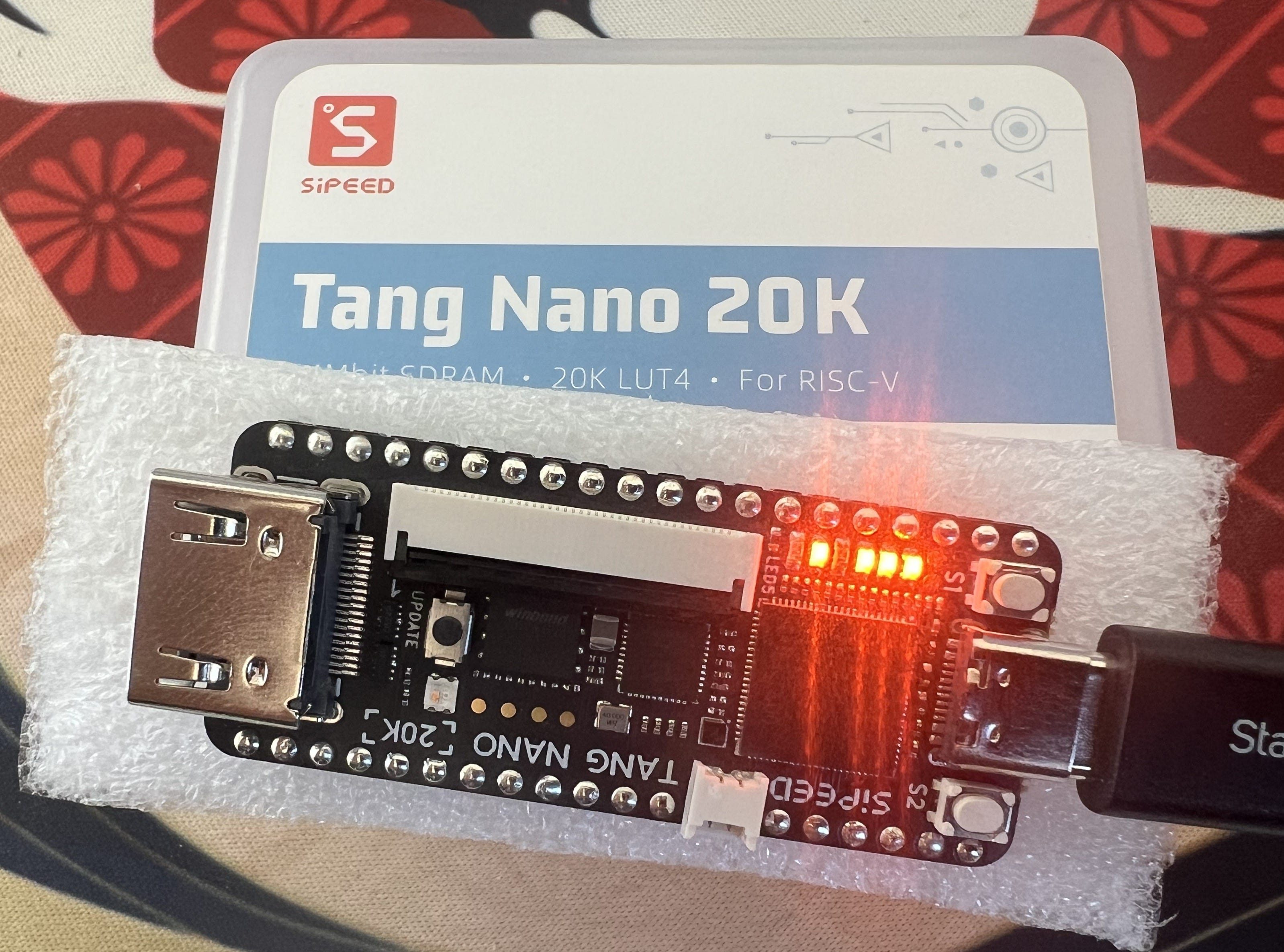
I picked up a Tang Nano 20K from Sipeed to get hands on with FPGA design and system architecture. Getting the thing to flash LEDs was not difficult thanks to LushayLabs wonderful documentation of the Nano 9k. Their article walks through a setup to replace the GowinIDE with VSCode. The workflow relied on LushayLab’s own VSCode Extension to program the Tang Nano 9k. While I was able to get an IDE experience with dark mode and syntax highlighting, it’s not exactly the development environment I’m looking for.
IDE projects are fine for a quick start, but they don’t scale. Each click in a GUI becomes a hidden state – something you can’t version, diff, or reproduce later. When projects need to build from the same source files onto multiple FPGAs, GUI projects will require separate repositories for the same design. I want something reproducible so I can version-control, automate, and run entirely from the terminal. So I took apart Gowin EDA on macOS, built a shell shim to load its dynamic libraries, and wired up a Tcl + Makefile pipeline that synthesizes, places, routes, and flashes the bitstream.
My goal is to eventually move entirely to an open source stack for the Gowin FPGA, but for now I will use the GowinIDE (free but licensed) to synthesize my design and generate a bitstream. This is made possible by the TCL interface, which provides a standardized tool automation interface similar to a shell. It’s a piece of shit, but it allows us to script the project creation and store diffs in source control.
I have attempted this automation process a few years ago with the Xilinx tools, but that work is behind me. The most valuable thing I learned from that process is that the tools suck all across the board. The FPGA IDE’s lack many of the modern conveniences, but as a software they seem to be frozen in 2012. It’s almost as if serious FPGA projects need to automate around them. Things are not all bad, however: MacOS is being increasingly supported as a viable platform for FPGA Development. I’m going to make this system work for my MacBook M2 Max.
TCL Interface
Gowin’s toolchain exposes a TCL interface that feels like a shell. You can type commands, set variables, and execute flows interactively, but it isn’t a true system shell. It runs inside the IDE’s own embedded TCL interpreter, with its own environment, command set, and limited filesystem access. Instead of scripts like bash or zsh, you write .tcl files that the interpreter executes line by line to create projects, add sources, and drive synthesis or place-and-route. In other words you’re scripting the FPGA tool itself. Automating the flow becomes as simple as defining a repeatable set of TCL commands and invoking them through the IDE’s command-line wrapper.
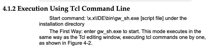
The Quick Start Guide gives me a windows path, but where did Gowin put their TCL interpreter on my Mac? MacOS applications that bundle in a .app, like GowinIDE, generally contain supporting binaries in the Application Contents. Performing a quick search for gw_sh I found:
/Applications/GowinIDE.app/Contents/Resources/Gowin_EDA/IDE/bin/gw_shRunning it directly in the shell complains about missing dynamic libraries. The shell needs to have pointers to the right binaries in Contents/Resources/GowinEDA/IDE/lib/.
Thankfully, there’s a env.zshrc file to give us a hint
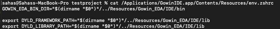
sourcing that file, allows us to run the gw_sh utility perfectly fine.

Getting Something to Build & Program
Now that the TCL interface has been located, we need to script a project. Gowin has documentation for automation in a PDF on their website. Feeding that to ChatGPT, along with a copy of my top.v (a simple Verilog counter module), I got it to generate some almost-working code. Massaging the build script by referencing the TCL documentation, I came up with this build script for my little project.
# ============================================================
# build.tcl — Automated Gowin Build Script
# ============================================================
# 1. Creates a project
# 2. Adds top.v
# 3. Creates and generates an IP
# 4. Runs synthesis and place & route
# ============================================================

# --- USER PARAMETERS ----------------------------------------
set prj_name “counter”
set prj_dir “/Users/sahas/workplace/fpga/testproject/gowin_project”
set top_name “top”
set device “GW2AR-LV18QN88C8/I7”
set device_version “C”

# --- CREATE PROJECT -----------------------------------------
create_project -name $prj_name -dir $prj_dir -pn $device -device_version $device_version -force

# --- ADD DESIGN SOURCE --------------------------------------
add_file /Users/sahas/workplace/fpga/testproject/top.v
add_file /Users/sahas/workplace/fpga/testproject/constraints.cst
set_option -top_module $top_name

# --- SYNTHESIS OPTIONS --------------------------------------
set_option -verilog_std sysv2017
set_option -global_freq 100
set_option -print_all_synthesis_warning 1

# --- PLACE & ROUTE OPTIONS ----------------------------------
set_option -timing_driven 1
set_option -gen_sdf 1
set_option -gen_verilog_sim_netlist 1
set_option -gen_text_timing_rpt 1
set_option -gen_io_cst 1
set_option -show_all_warn 1

# --- RUN FLOWS ----------------------------------------------
run all
# Alternatively:
#run syn
#run pnr

# --- SAVE SCRIPT SNAPSHOT -----------------------------------
saveto -all_options build_snapshot.tcl

# --- CLOSE PROJECT ------------------------------------------
run close
Once I could generate a bitstream, the next challenge was programming the board entirely from the command line. The official Gowin Programmer is GUI only. It works, but it doesn’t fit the goal of a source-controlled, fully scriptable flow. I first looked at the LushayLabs tutorial, which uses a VS Code extension and WebUSB interface to load the bitstream, but that approach still depends on a graphical environment. The Gowin Programmer documentation also doesn’t expose any clear command-line hooks or API.
So instead, I turned to the open source openFPGALoader project, which supports the Tang Nano 20K directly. I’m pleasantly surprised the open source solution was the simplest and most reliable solution for a scriptable flow. Installing the full open source toolchain from GitHub, where I will eventually migrate to, on macOS was straightforward. Within minutes I could detect and flash the board straight from the terminal.


Putting the Pieces Together
At this point, I needed a way to tie simulation, synthesis, and flashing into one reproducible workflow. The only tool that truly makes sense for FPGA projects, regrettably, is the Makefile. It’s primitive, but it’s universal, predictable, and plays well with both Tcl and Python.
TOPLEVEL_LANG = verilog
VERILOG_SOURCES = $(PWD)/src/top.v
TOPLEVEL = top
MODULE = tests.test_top

SIM ?= icarus

include $(shell cocotb-config --makefiles)/Makefile.sim

# Gowin EDA paths
GOWIN_SHELL ?= $(CURDIR)/gw_sh_wrapper.sh
OPENFPGALOADER ?= /opt/oss-cad-suite/bin/openFPGALoader
BITSTREAM_PATH = gowin_project/counter/impl/pnr/counter.fs

.PHONY: test clean build program

# Run cocotb simulation (produces waves.vcd via RTL dump block)
test: sim

# Build FPGA bitstream using Gowin EDA
build: build/build.tcl build/constraints.cst src/top.v
    $(GOWIN_SHELL) $(CURDIR)/build/build.tcl

# Program FPGA using openFPGALoader
program: $(BITSTREAM_PATH)
    $(OPENFPGALOADER) -b gowin $(BITSTREAM_PATH)

# Remove cocotb build outputs, waveform, and Gowin build artifacts
clean::
    $(MAKE) -f $(shell cocotb-config --makefiles)/Makefile.sim clean || true
    rm -rf sim_build waves.vcd __pycache__ .pytest_cache
    rm -rf impl *.fs *.log *.json
    rm -rf gowin_project build_snapshot.tcl
Unlike vendor GUIs, make gives you composable, scriptable control over every stage of the flow:
make testruns cocotb simulationmake builddrives Gowin’s Tcl synthesis and place-and-routemake programflashes the bitstream to the board via openFPGALoader.
The final project structure reflects that logic: a clean separation between build scripts (build/), design sources (src/), tests (tests/), simulation outputs (sim_build/), and the generated Gowin project directory (gowin_project/). It’s not pretty, but it’s reproducible and a flexible base for more complicated designs.
You can find the Github here with the full code that worked for me.
Conclusions
I’ve never consistently had a terrible experience with developer tools until the FPGA world. The industry agrees, every conference about FPGAs will have a session or two on how “the tools are bad,” but setup for the Gowin FPGA actually went pretty smoothly. The fact that I can have a full working toolchain on MacOS is a huge step forward, but MacOS still unsupported by the big FPGA manufacturers (Xilinx/Altera).
Setting up a repository like this is step 1 in any serious development. However, these housekeeping steps are usually baked in dev tools by the time most people will join a project. It’s for this reason Computer Engineering curriculums will teach the basics of logic design, but leave students with no understanding of how to design from scratch. This is the same educational error in the software world where engineering from 0 is a critical skill. In my experience, I’ve seen senior engineers spin up a API with load balancers, database, and logic in a weekend with their tools, but feel useless once they leave their company and access to the company tools.
It’s a question of what is step 0 to you? If you ask working engineers, they’re not concerned with setting up new tools or new ways of doing things, they’re busy with KPIs, delivery timelines, and management. It’s rare that an engineer needs to build from 0, but to me it’s the most fun. Zero means every architecture decision, every tooling decision, and every hiccup or misconception will affect the future of that project. Nobody likes to inherit another person’s “from zero” project as it usually means onboarding to bad code and unique architecture decisions. Does this mean I’ll be stuck in R&D cycles with nothing I make hitting production? Probably, until I can break that barrier with an idea.